Product Help

Help and Information for the Brands that we sell
FESTO PRODUCTS
Push-in fittings for pneumatics
Pneumatic push-in fittings are the standard on the pneumatic fittings market and are very widely used. What sets them apart is the easy release function for the tube, i.e. by pressing a releasing ring. These fittings are used with the standard O.D. tubing that is commonly available on the market.
-
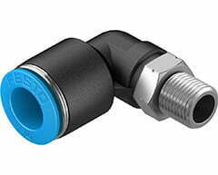 Festo Push-in L-fitting QSL-1/8-10, 190658£4.52 Exc. VAT £5.42 Inc. VAT
 -
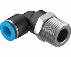 Festo Push-in L-fitting QSL-1/2-10, 190661£7.32 Exc. VAT £8.78 Inc. VAT
 -
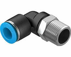 Festo Push-in L-fitting QSL-3/8-10, 153052£5.14 Exc. VAT £6.17 Inc. VAT
What are sensors and What types of sensors are there?
A sensor is a component that converts a measured physical variable or a chemical effect into an analogue electrical output signal. The physical variable is an input signal that is not electrical, such as pressure, weight, temperature, radiation, magnetic flow, speed or another physical variable. There are different types of sensor, such as:
- Position transmitters
- Pressure and vacuum sensors
- Flow sensors
- Cylinder sensors
- Inductive proximity switches
- Opto-electrical sensors
-
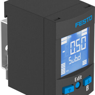 SPAU-V1R-W-Q4D-L-PNLK-PNVBA-M8D pressure sensor 8001239£122.57 Exc. VAT £147.08 Inc. VAT
 -
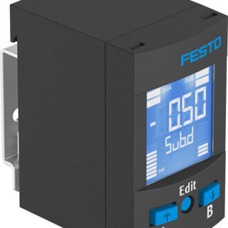 SPAU-V1R-W-Q4D-L-PNLK-PNVBA-M12D pressure sensor 8001238£125.76 Exc. VAT £150.91 Inc. VAT
 -
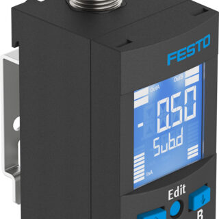 SPAU-V1R-W-G18FD-L-PNLK-PNVBA-M8U pressure sensor 8001235£127.67 Exc. VAT £153.20 Inc. VAT
The MS series filter regulator
This series offers the widest range of filter regulator units, ideal for every application. With good particle separation at a high flow rate and good control characteristics with a low hysteresis. A return flow function and secondary exhaust are integrated as standard in the MS series.
The filter regulator can be installed as a module in service units thanks to the simple modular system of the MS series. Four sizes offer a wide flow range.
The housings are made of die-cast aluminium, the filter bowls are either made of metal or polycarbonate with a bowl guard and can be combined with all condensate drain systems.
The filter regulators MS-LFR can optionally be configured for use in potentially explosive areas of zones 1, 2, 21 and 22 as well as with UL approval.
-
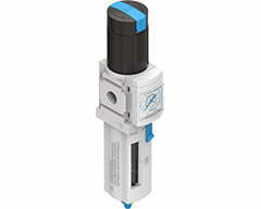 Festo filter regulator MS4-LFR-1/8-D7-ERV-AS, 529174£92.57 Exc. VAT £111.08 Inc. VAT
 -
 Festo filter regulator MS4-LFR-1/8-D6-ERV-AS, 529166£92.57 Exc. VAT £111.08 Inc. VAT
What is a Pressure Gauge?
A pressure gauge is a method of measuring fluid, gas, water, or steam intensity in a pressure powered machine to ensure there are no leaks or pressure changes that would affect the performance of the system. These systems are designed to operate within a specific pressure range. Any deviation from the acceptable norms can seriously affect the workings of the system.
Pressure gauges have been used for more than a hundred years and have been constantly evolving to fit the needs of new applications, many techniques. The implementation and use of pressure gauges has made them a necessity as more and more pressure systems become operational.
Types of Pressure Gauges
The variations are dependent on where the gauge will be used, with different sizes, styles, and materials designed to fit specific applications. There are several ways pressure gauges are categorized and defined, including by usage, and media.
Total pressure is determined by the perpendicular force applied per unit area of a surface, a calculation that is determined through the use of different techniques and methods. The correct measurement of pressure is dependent on the reference the pressure reading is measured against. They are divided into hydrostatic and mechanical.
Hydrostatic Pressure is generated by the weight of a liquid above a measurement point when the liquid is at rest. The height of the liquid influences the hydrostatic pressure. The hydrostatic properties of a liquid are not constant and are influenced by liquid density and gravity, (both of which determine hydrostatic pressure).
Mechanical Pressure is measured by a bellows, diaphragm, or Bourdon tube that converts fluid pressure into force.
In the discussion of pressure, it is important to understand some of pressure‘s other dynamics, which are absolute, gauge, differential, and atmospheric. Everyone is familiar with ambient atmospheric pressure; it is discussed as part of weather reports, it is the pressure of the air around us. Absolute, differential, and gauge pressure are methods for measuring pressure.
Absolute Pressure is when pressure is measured relative to a vacuum.
Gauge Pressure is pressure relative to the ambient atmospheric pressure. This form of pressure is positive when it is above atmospheric pressure and negative when it is below atmospheric pressure.
Differential Pressure is measuring the difference between two types of applied pressure. This form of pressure measurement does not have a reference but measures the two applied pressures.
-
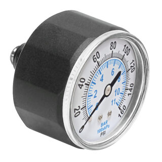 Pressure Gauge 527405 MA-27-160-M5-PSI£12.16 Exc. VAT £14.59 Inc. VAT
 -
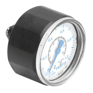 Pressure Gauge 526324 MA-27-1,0-M5-MPA£12.16 Exc. VAT £14.59 Inc. VAT
 -
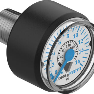 Pressure Gauge 183896 MA-23-6-R1/8£13.13 Exc. VAT £15.76 Inc. VAT
What is a pneumatic valve?
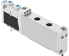
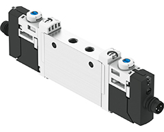
Like any valve, pneumatic valves have a control function to determine the amount of gas or compressed air that is allowed to flow through. With a pneumatic valve, the flow is controlled by a pneumatic signal.
-
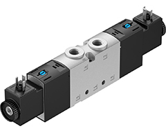 Festo VUVS-LT30-T32U-MZD-G38-F8-1C1 solenoid valve 8036710£123.40 Exc. VAT £148.08 Inc. VAT
 -
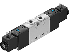 Festo VUVS-LT30-T32U-MZD-G38-F8-1B2 solenoid valve 8036712£123.40 Exc. VAT £148.08 Inc. VAT
 -
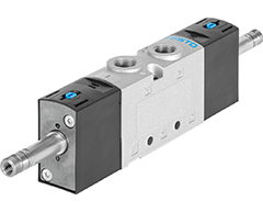 Festo VUVS-LT30-T32U-MZD-G38-F8 solenoid valve 8036708£100.78 Exc. VAT £120.94 Inc. VAT
What is the difference between electric and pneumatic valves?
Electric pilot-actuated valves or pneumatic valves can be used to control actuators. Electric pilot-actuated valves can be operated with 12 V, 24 V or 230 V. Common variants are, for example, 3/2- or 5/2-way valves.
Pneumatic valves, on the other hand, are actuated by compressed air.
-
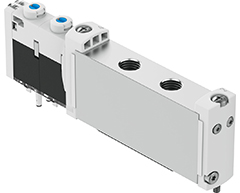 Festo VUVG-S18-T32U-MZT-G14-1T1L solenoid valve 8004877£114.74 Exc. VAT £137.69 Inc. VAT
 -
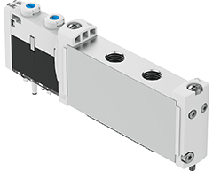 Festo VUVG-S18-T32U-AZT-G14-1T1L solenoid valve 8004874£108.26 Exc. VAT £129.91 Inc. VAT
 -
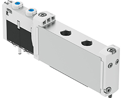 Festo VUVG-S18-T32H-MZT-G14-1T1L solenoid valve 8004878£114.74 Exc. VAT £137.69 Inc. VAT
What is the purpose of directional control valves?
A directional control valve is used to change, open or close the flow of a medium in a hydraulic or pneumatic system. Compressed air or a hydraulic fluid is the fluid that is normally used. The task of a directional control valve is thus to release, change or block cross-sections in the valve for the liquid or gas (fluid).
Standards-based directional control valves
Electric or pneumatic directional control valves can be used to control actuators. Mechanically actuated valves can be actuated using 12, 24, 110 and 230 V. Common variants are, for example, 3/2- or 5/3-way valves. Mechanically operated directional control valves are switched by a button, a lever, a pedal or a spring, for example. Pneumatic valves, on the other hand, are actuated by compressed air.
Standards-based directional control valves from Festo are available with electric or pneumatic actuation.
-
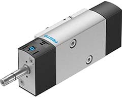 Festo Solenoid valve VSNC-FTC-M52-MD-N14-FN, 577279£81.89 Exc. VAT £98.27 Inc. VAT
 -
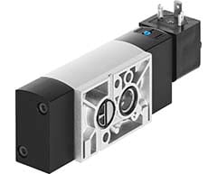 Festo Solenoid valve VSNC-FTC-M52-MD-G14-FN-1A1, 577297£93.82 Exc. VAT £112.58 Inc. VAT
 -
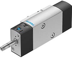 Festo Solenoid valve VSNC-FTC-M52-MD-G14-FN, 577277£81.89 Exc. VAT £98.27 Inc. VAT
What is a 3/2-way valve?
Directional control valves differ in terms of the number of ports and switching positions. A 3/2-way valve is used to switch a single-acting actuator, for example to switch a media flow and relieve the secondary side when the valve closes.
Festo 3/2-way valves are available in normally closed (NC) and normally open (NO) positions.
-
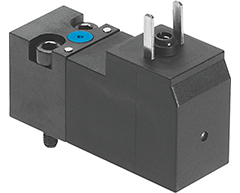 Festo VSCS-B-M32-MH-WA-5C1 3/2 closed, monostable solenoid valve 546257£30.02 Exc. VAT £36.02 Inc. VAT
 -
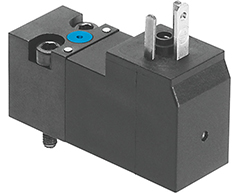 Festo VSCS-B-M32-MH-WA-3AC1 3/2 closed, monostable solenoid valve 546260£30.02 Exc. VAT £36.02 Inc. VAT
 -
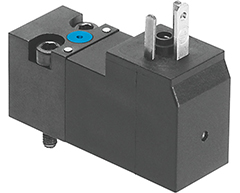 Festo VSCS-B-M32-MH-WA-2AC1 3/2 closed, monostable solenoid valve 546259£30.02 Exc. VAT £36.02 Inc. VAT
BURKERT PRODUCTS
Type 2000 Angle Seat Valves
Pneumatically operated 2/2 way angle seat valve CLASSIC
Stainless steel or gunmetal housing with threaded, clamped or welded connection
Long service life
High flow rate
Robust actuators with modular accessory program
The externally piloted angle seat valve is operated with a single or double acting piston actuator. The actuator is available in two different materials, depending on the ambient temperature. High flow rates are attained with the virtually straight flow path. The reliable self-adjusting packing gland provides high sealing integrity. These maintenance-free and robust valves can be retrofitted with a comprehensive range of accessories for position indication, stroke limitation or manual override.
-
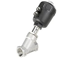 Burkert Type 2000 1/2″ BSP 2/2-way angle seat valve, 178603£253.00 Exc. VAT £303.60 Inc. VAT
 -
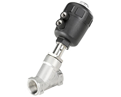 Burkert Type 2000 3/8″ BSP 2/2-way angle seat valve, 142613£253.00 Exc. VAT £303.60 Inc. VAT
 -
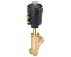 Burkert Type 2000 2″ BSP 2/2-way angle seat valve, 140142£362.00 Exc. VAT £434.40 Inc. VAT
Type 6012 – Plunger valve 3/2 way direct-acting
Valve 6012 is a direct-acting plunger valve. The stopper and plunger guide tube are welded together to enhance pressure resistance and leak-tightness. Various seal material combinations are available depending on the application. A Burkert-specific flange design (SFB) enables space-saving arrangement of valves on a manifold. Push-in fittings can be selected for flexible hose connection. A banjo connection with banjo bolt is the ideal solution for easy direct mounting on a pneumatic drive. Optional manual actuation enables quick commissioning and optimal maintenance. In combination with a cable plug in accordance with industry standard Form B or DIN EN 17301-803 Form C, the valves satisfy protection class IP65.
Direct-acting, compact small-format valve with diameter of up to DN 1.6
Screwed coil system
Banjo threaded connection for direct mounting on pneumatic valves
Simple and quick push-in, flange, or manifold installation
Service-friendly manual override
-
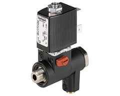 Burkert Type 6012 1/4″ BSP 3/2 Banjo Valve 24VAC, 552292£83.10 Exc. VAT £99.72 Inc. VAT
 -
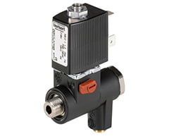 Burkert Type 6012 1/4″ BSP 3/2 Banjo Valve 110VAC, 552293£83.10 Exc. VAT £99.72 Inc. VAT
 -
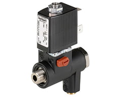 Burkert Type 6012 1/4″ BSP 3/2 Banjo Valve 24VDC, 552291£83.10 Exc. VAT £99.72 Inc. VAT
Type 1060 Electrical position feedback for pneumatically operated process valves
The Type 1060 is designed for integrated mounting on CLASSIC Series process valves. Due to its simple and a very compact design, the position feedback can easily be mounted on a valve. Depending on the switch type of the electrical position feedback, the positions of the valve are reported electrically: open, closed.
Fast and easy installation
Compact design
-
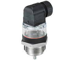 Burkert Type 1060 Optical Position Indicator 100mm, 701516£80.90 Exc. VAT £97.08 Inc. VAT
 -
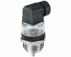 Burkert Type 1060 Optical Position Indicator 80mm, 701515£70.00 Exc. VAT £84.00 Inc. VAT
Type 2051 Pneumatic rotary actuator
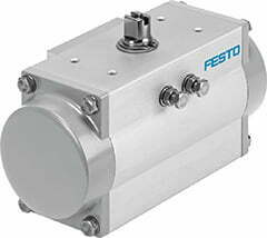
The Type 2051 pneumatic rotary actuators are low maintenance single or double acting pneumatic linear piston actuators where linear movement of the piston due to the pilot air causes a 90º rotation of the connected valve. Actuator-valve coupling is made via a universal ISO 5211 mechanical interface. The status of ball or butterfly valve can be monitored via the feedback switches of 1061. Moreover the actuator can be used as modulating control actuator by the addition of Burkert’s range of Side Control positioners 8792/3.
- Modular program for mounting of quarter turn valves such as ball valves and butterfly valves
- NAMUR and ISO 5211 interfaces
- Position feedback with Type 1061 possible (also for Ex-applications)
- Side Control Positioner ready – Type 8792/3
- ATEX 2014/34/EU
-
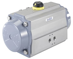 Burkert Type 2051 Actuator Double Acting Size 100, 214525£227.00 Exc. VAT £272.40 Inc. VAT
 -
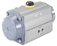 Burkert Type 2051 Actuator Double Acting Size 220, 214527£387.00 Exc. VAT £464.40 Inc. VAT
 -
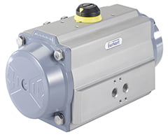 Burkert Type 2051 Actuator Double Acting Size 30, 214522£137.00 Exc. VAT £164.40 Inc. VAT
INOXPA PRODUCTS
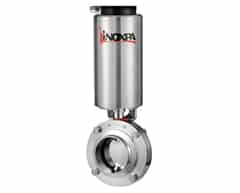
Sanitary butterfly valves A480
Whether manually or automatically operated, can be used in most liquid product applications in the food-processing, pharmaceutical and chemical industries. The design of the butterfly valve between flanges A490 facilitates its installation and maintenance, allowing the extraction of the valve by means of 4 screws while the flanges welded to the installation remain fixed.
Sanitary butterfly valves can be operated automatically through an actuator (sanitary pneumatic butterfly valve, sanitary butterfly valve with pneumatic actuator) or manually with a handle. The handle blocks the valve in the “open” or “closed” position, although there are also other models with intermediate positions. The actuator transforms the axial movement of the piston into a 90º rotary movement which it transmits to the disc.
-
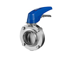 Inoxpa 4″ RJT Butterfly Valve EPDM, VA486-110652101£264.00 Exc. VAT £316.80 Inc. VAT
 -
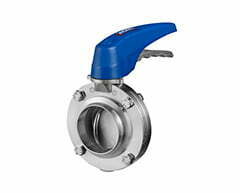 Inoxpa 3″ RJT Butterfly Valve EPDM, VA486-110652076£158.00 Exc. VAT £189.60 Inc. VAT
 -
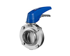 Inoxpa 21/2″ RJT Butterfly Valve EPDM, VA486-110652063£128.00 Exc. VAT £153.60 Inc. VAT
MARS VALVE PRODUCTS
What is a Ball Valve
A ball valve is a flow control device which uses a hollow, perforated, and pivoting ball to control fluid flowing through it. It is open when the hole through the middle of the ball is in line with the flow inlet, and closed when it is pivoted 90 degrees by the valve handle, blocking the flow. The handle lies flat in alignment with the flow when open, and is perpendicular to it when closed, making for easy visual confirmation of the valve’s status. The shut position 1/4 turn could be in either clockwise or counter-clockwise direction.
Ball valves are durable, performing well after many cycles, and reliable, closing securely even after long periods of disuse. These qualities make them an excellent choice for shut-off and control applications, where they are often preferred to gates and globe valves.
-
 Mars 50-10 3 Piece Steam Duty Ball ValvePrice range: £24.50 through £576.00
CMO PRODUCTS
What is a knife gate valve
A knife gate valve is a type of gate valve that uses a knife-like edge to cut through materials and stop flow. The valve is designed to work in harsh environments, such as wastewater applications where corrosion is a concern. It’s also useful for thick fluids, dry bulk solids, and high-viscosity slurries like paper pulp.
CMO AB Series knife gate valves are designed for applications such as: Industry, Chemical plants, Pumping, Food industry and Clean water treatment.
ADCA PRODUCTS
What is a steam trap
A steam trap is a device used to discharge condensates and non-condensable gases with a negligible consumption or loss of live steam. Steam traps are nothing more than automatic valves. They open, close or modulate automatically.[1] The three important functions of steam traps are:
Discharge condensate as soon as it is formed (unless it is desirable to use the sensible heat of the liquid condensate)
Have a negligible steam consumption (i.e. be energy efficient)
Have the capability of discharging air and other non-condensable gases.
Basic operation
The operation of a steam trap depends on the difference in properties between steam and condensate. Since liquid condensate has a much higher density than gaseous steam, it will tend to accumulate at the lowest possible point in the steam system. Steam properties such as density, latent heat, and saturation/boiling point are affected by pressure.
Steam traps can be split into three main categories; Mechanical, Thermodynamic, and Thermostatic. Each type uses a different operating principle to remove condensate and non-condensable gases and keep steam in the system. The vast majority of steam traps in current operation are of the mechanical operated design.
Steam traps are sized for specific applications based on amount of condensate they can remove, as well as other factors such as the ability to remove air and non-condensable gases.
-
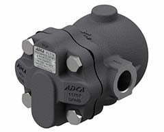 Adca FLT16-10 1/2″ BSP Ball and Float Steam Trap A.25.1403.015£162.00 Exc. VAT £194.40 Inc. VAT
 -
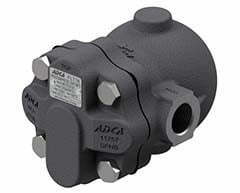 Adca FLT16-10 3/4″ BSP Ball and Float Steam Trap A.25.1403.020£168.00 Exc. VAT £201.60 Inc. VAT
 -
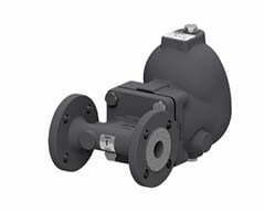 Adca FLT25-10 1″ BSP Ball and Float Steam Trap A.253.VXXXXIR.A25£319.00 Exc. VAT £382.80 Inc. VAT
What is a pressure reducing valve used for
A pressure reducing valve (PRV) is an automatic control valve that regulates the pressure of liquids like water, steam, or oil and gas. PRVs are used to reduce pressure from a higher inlet to a lower outlet pressure, and to maintain that lower pressure even when inlet pressure or demand changes. PRVs are often used in pipelines to ensure that downstream components aren’t damaged by high pressure.
Where should a pressure reducing valve be used?
They are normally installed on the main water line next to the shut-off valve. As the water flows through the valve, it passes through the diaphragm that is connected to a spring and reduces the pressure to the desired level as the water moves from the valve through the other side.
-
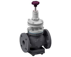 Adca PRV57 3″ DN80 Pressure Reducing Valve, PRV5780B£3,750.00 Exc. VAT £4,500.00 Inc. VAT
 -
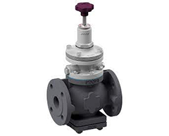 Adca PRV57 21/2″ DN65 Pressure Reducing Valve, PRV5765R£2,996.00 Exc. VAT £3,595.20 Inc. VAT
 -
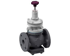 Adca PRV57 2″ DN50 Pressure Reducing Valve, PRV5750R£1,996.00 Exc. VAT £2,395.20 Inc. VAT
What are Sensor pockets
Sensor pockets, also known as thermowells, are protective housings that are used to measure temperature in liquids in pipework or in other systems. They are often used in industrial processes and systems to measure temperature in corrosive, high-pressure, or high-velocity environments. Sensor pockets are designed to isolate the temperature sensor from the process fluid or gas, allowing the sensor to accurately measure the temperature while protecting it from direct contact with the process media.
Sensor pockets can be made from a variety of materials, including brass, stainless steel, and metal: Brass: Can be used with standard LPHW and DHWS systems. JTM brass sensor pockets can accommodate sensors of 7mm to 9mm diameters and screw securely into a range of standard brass fittings.
Stainless steel: Can be used on high temperature and pressure installations (including steam) and are also recommended for chilled water and other low temperature applications. For example, AEI Group offers stainless steel pockets that are designed to accept 150 x 6mm diameter sensor probes and are locked in position by a grub screw.
Metal: Can be cylindrical or tapered and inserted into a process pipe or vessel.
Sensor pockets can also be used in conjunction with self-acting thermostats with rod sensors. In these applications, sensor pockets can secure quick heat transfer from media to the thermostat sensor, making it easier to change the sensor.
-
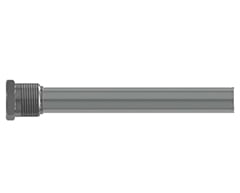 ADCA PK2 St/St Pocket T.205 Thermostat, Type PK2, TR.9015.002£109.00 Exc. VAT £130.80 Inc. VAT
 -
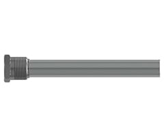 ADCA PK4 St/St Pocket T.405 Thermostat Type PK4, TR.9015.004£115.00 Exc. VAT £138.00 Inc. VAT
SEKO PRODUCTS
What is a dosing pump
Dosing pumps, also known as metering pumps, are used to accurately add a specific volume of chemicals or solutions to a process. They can be used in many industries, including water treatment, food, petrochemicals, agriculture, and manufacturing.
Dosing pumps can be used for a variety of applications, including: Neutralizing pH levels: Adding corrosive chemicals or acids to water storage tanks. Killing bacteria: Using chlorine to kill bacteria, Disinfecting: Using sodium hypochlorite to disinfect, Producing fertilizer: Using phosphoric acid to react with minerals in phosphate rock to produce phosphate salts.
Dosing pumps are designed to operate in challenging conditions, such as high temperatures and high pressures. They can often be used in combination with sensors to adjust their speed or stroke length in response to changing chemical conditions.
The type of dosing pump used depends on the required metering accuracy. Some common types of dosing pumps include diaphragm pumps, peristaltic pumps, and lobe pumps.
-
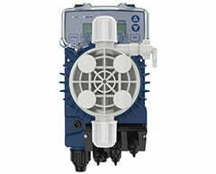 Seko TPG803NHH0007 Tekna Evo Digital Dosing Pump, TPG803£794.00 Exc. VAT £952.80 Inc. VAT
 -
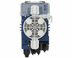 Seko TPG603NHH0020, Tekna Evo Digital Dosing Pump, TPG603£598.00 Exc. VAT £717.60 Inc. VAT
 -
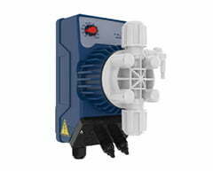 Seko AML200NHE0000, Kompact Analogue Dosing Pump, AML200£229.00 Exc. VAT £274.80 Inc. VAT
How does a dosing pump work
A dosing pump, also known as a metering pump, draws a specific amount of liquid into a chamber and then injects it into a pipe or tank that contains the fluid being dosed. The pump is powered by an electric motor or air actuator and has a controller that manages the flow rate and turns the pump on and off.
Here’s how a dosing pump works:
Adding fluid
The displaced fluid is then added to the process stream at the desired point.
Suction
The pump draws in the fluid to be dosed from a storage container or reservoir.
Displacement
The fluid moves through a tube or chamber where the volume is controlled or fixed.
Mixing
The solution is mixed to the correct dosing ratio within the chamber.

